Why is Position used?
A hole can meet its diameter limit but still miss a mating fastener. Position controls the assembled pattern in a way that coordinate size limits alone do not express clearly.
 Engineering toolkit · Prototype
LOCATION CONTROL / GD&T SYMBOL GUIDE
The position tolerance, sometimes called true position, is the most widely used geometric tolerance. It controls the location of a feature of size, with the requirement applied to its axis or centre plane. The tolerance zone may be a circle, cylinder, sphere, area between two parallel lines, or space between two parallel planes.
When a positional tolerance is applied to a feature, dimensions locating that feature must be basic dimensions because the locational tolerance applies directly to the feature. Basic dimensions give the theoretically exact location of the tolerance zone, not the actual feature.
INTERACTIVE APPLICATION
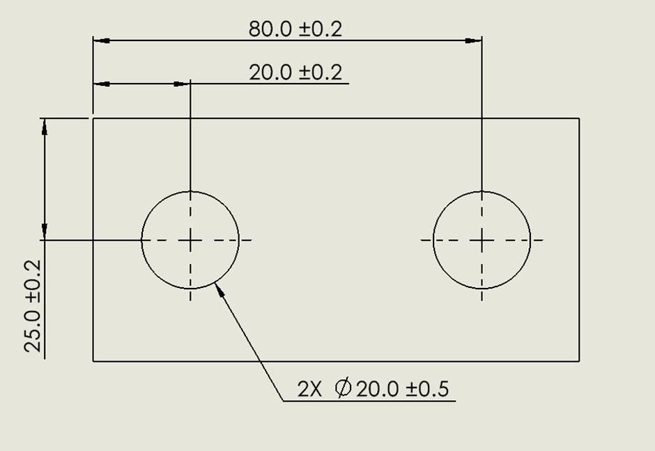
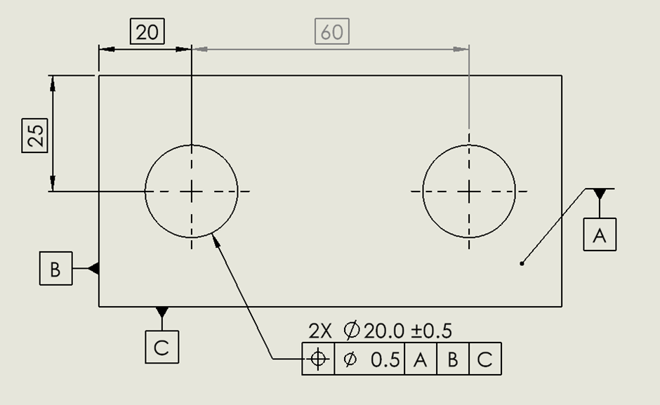
A hole can meet its diameter limit but still miss a mating fastener. Position controls the assembled pattern in a way that coordinate size limits alone do not express clearly.
Position tolerance is commonly applied to features of size: holes, pins, bosses, slots, tabs and hole patterns. It controls their location, and often orientation, relative to a datum reference frame. It is not normally used to control general surface form; profile tolerance is usually more appropriate for surface location and form.
Establish datums A, B and C, give the hole centres basic dimensions, and attach the position frame to the hole-pattern size callout. The ⌀0.5 value defines a cylindrical zone for each derived hole axis. No material modifier is assumed here.
Each hole axis lies within a ⌀0.5 mm cylinder at its basic location in the A–B–C datum reference frame.
The illustrated ⌀0.5 mm control is a tighter choice than the ⌀0.57 mm zone needed to enclose the full ±0.2 mm X/Y corner spread.
Find the position symbol first. Read the zone size and shape next: ⌀0.5 means a cylindrical zone 0.5 mm across. Check for a material condition modifier; none is shown in this example. Read the datum references in order, A | B | C, then use the basic dimensions to find the theoretically exact position.
The zone symbol changes what is controlled. A diameter sign specifies a diametral zone; a plain width specifies separation between parallel boundaries. The drawings below are simplified sections of three-dimensional zones.
Hole or pin axis
The derived axis stays within a cylinder centred on its basic location.
Slot or tab centre plane
The derived centre plane stays between two parallel planes. In a section view, these appear as two lines.
Centre point of a sphere
The derived centre point stays inside a sphere centred on its basic location.
The controlling value is a tolerance-zone width, not a universal process grade. For this position example, the drawing states the controlled feature and applicable extent.
Scroll the table sideways to see every column.
| Application | Illustrative starting value | Example feature | Notes / caution |
|---|---|---|---|
| General clearance-hole pattern | ⌀0.20–0.50 mm | Four M8 clearance holes | Check bolt clearance and datum scheme. |
| Dowel location | ⌀0.05–0.15 mm | Ø8 mm locating bore | Account for mating-part stack-up. |
| Large fabricated hole pattern | ⌀0.5–1.5 mm | 500 mm frame | Check process and fixture distortion. |
These are planning examples, not universal rules or guaranteed process capabilities. Set the actual tolerance from function, size, length, process capability, inspection method and the standard specified on the drawing.
Compare the measured feature axis, centre plane or centre point with the theoretically exact position established by the basic dimensions and datum reference frame.
ASME Y14.5 uses basic dimensions and an ordered datum reference frame to locate position zones. Bonus tolerance applies only when a valid material-condition modifier is explicitly specified.
ASME Y14.5 edition reference. Examples are learning schematics; use the complete requirements on the drawing.
LEARN BY DOING
The INTERFAIC interactive GD&T course is coming soon.